Lost Connection!
Trying to reconnect in ...
Please wait or click button below.
This time I am sharing a series that is old school or means it has been around for a long time but we just made it. What's that?
Series of Turning On Equipment With TV Remote. If we have been around the world of electronics for a long time, of course we are bored with this circuit, but if friends who are just starting to learn the world of electronics, this is a simple circuit and everyone can make it. How to make it let's read the article below.


Like that circuit, using the Ne555 and 4017 ic and equipped with a 1 channel relay as a switch.

The function of the circuit: if we have a fan, for example, we turn on the fan by pressing the on/off button, but if given this circuit, it is enough to use the TV remote as a substitute for pressing the On/Off button, of course with the correct wiring. Makes it easier for us and makes us lazy to stand of course. The circuit is quite cheap with components that are easy to find in the market.

Components used :

IC : Ne555 dan 4017
Resistor : 
1 K
100 K
330 Ohm
Transistor : Bc547
Led : 3 mm green and red
Infrared Sensors
5v Relay Module

Friends who want to try, please, the circuit has been successfully created.


For important notes :
The output of IC4017 on leg no. 2 is given a 1 channel relay module, because the module has a LOW logic how it works, so in the IC 4017 output circuit I made it like the circuit above, "directing to ground" is different if the module is logic HIGH the output circuit is on leg number 2 different IC4017. If you don't understand, you can comment below

You can also see the video on youtube : Ajifahreza Channel


Some of my network reyjewish-electronic.blogspot.com Modification of Turning on Electrical Appliances Using TV Remote. Hopefully useful and share if useful

Arduino in terms of hardware is the name of a microcontroller board. Arduino was created with the aim of making it easier for us to experiment or create microcontroller-based equipment, for example :


  • Automatic plant watering
  • Water level monitoring
  • Sms gateway
  • People presence detector
And there are many more that have been developed. Currently, there are various types of Arduino boards, one of which is Arduino Mega2560. Even though there are various types of Arduino, in principle the programming remains the same, only the pins are different, because each has a different number of pins..

Arduino Mega2560
Arduino mega has a size of 10 cm x 5 cm. This board is recommended for use in projects that are more complex and use a lot of digital pins for I/O. 

Arduino Mega2560 Technical Information :

  • ATmega2560 IC
  • Digital 54 Pins, with 15 Pins (PWM)
  • Analog Pins 16
  • UART pins 4
  • 16 MHZ Crystal Oscillator
  • Reset button
  • Has a USB port, power jack and ICSP header
  • Flash memory 256 KB, SRAM 8 KB and EEPROM 4 KB

Explanation :
  • The USB port is used to connect Arduino to a computer
  • The DC jack is used for an external supply source when Arduino is not connected to a computer, if Arduino is connected to a computer then the power source comes from the computer. The input voltage from this source is between 7 Vdc - 12 Vdc
  • Digital pins 0 to 53 are called digital pins because they have two states, namely 1 and 0 or 5 V and 0 V. The maximum current is 20 mA
  • Analog Pin is an analog pin (continuous value) which has an analog value of 0 - 1023, commonly used for certain sensors
  • IC ATmega2560 as a processor
  • There are 2 pins that are used as supply voltages, for example for sensors that have an output value of 3.3 Vdc and 5 Vdc
  • ICSP (In-Circuit Serial Programming) is used to program Arduino through Arduino ISP
  • Flash memory is used to store code. 8 KB of this memory is used for the bootloader
  • SRAM (Static Random Access Memory) is used to hold data temporarily when data processing occurs
  • EEPROM (Erasable Programamble Read-Only) is used to store data permanently so that it is not lost if there is no power to Arduino.
  • The 16 MHZ Crystal Oscillator functions as a signal generator with a frequency of 16 MHZ
Arduino Mega2560 specifications
MicrocontrollerATmega2560
Operating Voltage5V
Input Voltage (recommended)7-12V
Input Voltage (limit)6-20V
Digital I/O Pins54 (of which 15 provide PWM output)
Analog Input Pins16
DC Current per I/O Pin20 mA
DC Current for 3.3V Pin50 mA
Flash Memory256 KB of which 8 KB used by bootloader
SRAM8 KB
EEPROM4 KB
Clock Speed16 MHz
LED_BUILTIN13
Length101.52 mm
Width53.3 mm
Weight37 g
Pinmap IC ATmega2560


Arduino Mega 2560 Pins IC
Pin NumberPin NameMapped Pin Name
1PG5 ( OC0B )Digital pin 4 (PWM)
2PE0 ( RXD0/PCINT8 )Digital pin 0 (RX0)
3PE1 ( TXD0 )Digital pin 1 (TX0)
4PE2 ( XCK0/AIN0 )
5PE3 ( OC3A/AIN1 )Digital pin 5 (PWM)
6PE4 ( OC3B/INT4 )Digital pin 2 (PWM)
7PE5 ( OC3C/INT5 )Digital pin 3 (PWM)
8PE6 ( T3/INT6 )
9PE7 ( CLKO/ICP3/INT7 )
10VCCVCC
11GNDGND
12PH0 ( RXD2 )Digital pin 17 (RX2)
13PH1 ( TXD2 )Digital pin 16 (TX2)
14PH2 ( XCK2 )
15PH3 ( OC4A )Digital pin 6 (PWM)
16PH4 ( OC4B )Digital pin 7 (PWM)
17PH5 ( OC4C )Digital pin 8 (PWM)
18PH6 ( OC2B )Digital pin 9 (PWM)
19PB0 ( SS/PCINT0 )Digital pin 53 (SS)
20PB1 ( SCK/PCINT1 )Digital pin 52 (SCK)
21PB2 ( MOSI/PCINT2 )Digital pin 51 (MOSI)
22PB3 ( MISO/PCINT3 )Digital pin 50 (MISO)
23PB4 ( OC2A/PCINT4 )Digital pin 10 (PWM)
24PB5 ( OC1A/PCINT5 )Digital pin 11 (PWM)
25PB6 ( OC1B/PCINT6 )Digital pin 12 (PWM)
26PB7 ( OC0A/OC1C/PCINT7 )Digital pin 13 (PWM)
27PH7 ( T4 )
28PG3 ( TOSC2 )
29PG4 ( TOSC1 )
30RESETRESET
31VCCVCC
32GNDGND
33XTAL2XTAL2
34XTAL1XTAL1
35PL0 ( ICP4 )Digital pin 49
36PL1 ( ICP5 )Digital pin 48
37PL2 ( T5 )Digital pin 47
38PL3 ( OC5A )Digital pin 46 (PWM)
39PL4 ( OC5B )Digital pin 45 (PWM)
40PL5 ( OC5C )Digital pin 44 (PWM)
41PL6Digital pin 43
42PL7Digital pin 42
43PD0 ( SCL/INT0 )Digital pin 21 (SCL)
44PD1 ( SDA/INT1 )Digital pin 20 (SDA)
45PD2 ( RXDI/INT2 )Digital pin 19 (RX1)
46PD3 ( TXD1/INT3 )Digital pin 18 (TX1)
47PD4 ( ICP1 )
48PD5 ( XCK1 )
49PD6 ( T1 )
50PD7 ( T0 )Digital pin 38
51PG0 ( WR )Digital pin 41
52PG1 ( RD )Digital pin 40
53PC0 ( A8 )Digital pin 37
54PC1 ( A9 )Digital pin 36
55PC2 ( A10 )Digital pin 35
56PC3 ( A11 )Digital pin 34
57PC4 ( A12 )Digital pin 33
58PC5 ( A13 )Digital pin 32
59PC6 ( A14 )Digital pin 31
60PC7 ( A15 )Digital pin 30
61VCCVCC
62GNDGND
63PJ0 ( RXD3/PCINT9 )Digital pin 15 (RX3)
64PJ1 ( TXD3/PCINT10 )Digital pin 14 (TX3)
65PJ2 ( XCK3/PCINT11 )
66PJ3 ( PCINT12 )
67PJ4 ( PCINT13 )
68PJ5 ( PCINT14 )
69PJ6 ( PCINT 15 )
70PG2 ( ALE )Digital pin 39
71PA7 ( AD7 )Digital pin 29
72PA6 ( AD6 )Digital pin 28
73PA5 ( AD5 )Digital pin 27
74PA4 ( AD4 )Digital pin 26
75PA3 ( AD3 )Digital pin 25
76PA2 ( AD2 )Digital pin 24
77PA1 ( AD1 )Digital pin 23
78PA0 ( AD0 )Digital pin 22
79PJ7
80VCCVCC
81GNDGND
82PK7 ( ADC15/PCINT23 )Analog pin 15
83PK6 ( ADC14/PCINT22 )Analog pin 14
84PK5 ( ADC13/PCINT21 )Analog pin 13
85PK4 ( ADC12/PCINT20 )Analog pin 12
86PK3 ( ADC11/PCINT19 )Analog pin 11
87PK2 ( ADC10/PCINT18 )Analog pin 10
88PK1 ( ADC9/PCINT17 )Analog pin 9
89PK0 ( ADC8/PCINT16 )Analog pin 8
90PF7 ( ADC7 )Analog pin 7
91PF6 ( ADC6 )Analog pin 6
92PF5 ( ADC5/TMS )Analog pin 5
93PF4 ( ADC4/TMK )Analog pin 4
94PF3 ( ADC3 )Analog pin 3
95PF2 ( ADC2 )Analog pin 2
96PF1 ( ADC1 )Analog pin 1
97PF0 ( ADC0 )Analog pin 0
98AREFAnalog Reference
99GNDGND
100AVCCVCC

Arduino Mega2560 circuit

Function Pins :
  • Serial 0 : 0 (RX) dan 1 (TX); Serial 1 : 19 (RX) dan 18 (TX); Serial 2 : 17 (RX) dan 16 (TX); Serial 3 : 15 (RX) dan 14 (TX)
  • PWM : 2 - 13  dan 44 - 46. 8 Bit PWM 
  • SPI : 50 (MISO), 51 (MOSI), 52 (SCK), 53 (SS)
  • LED : Pin13
  • TWI : 20 (SDA) dan 21 (SCL)
Mp3 player is a tool that is used to play mp3 format, so we find this a lot on branded music players, for example simbadda, polytron and others.


Actually we can make the tool easily and cheaply, not making it but assembling it because many of the modules are already being sold and the price is quite cheap. Cheaper than the price of your internet quota package maybe hehe. What kind of tool let's read the article below.
Previously, we had to buy a module, so we could get onlinek :
Module used : 
  • Mp3 Decoder Amplifier Audio Player Module

  • Speakers 4 Ohms / 10 Watts

  • Button 4 pcs

  • Usb Cable and Jumper Cable


After we buy the modules, we assemble them according to the circuit below

For Mp3 Player module specifications  below this :
Board Mp3 Player is suitable for installation on cars or modifications to motorbikes, Home Audio. Song files can be from flashdisk and SD Card. To turn on this mp3 module, you can use a power bank or battery charger with a voltage of 3.7 V - 5V. It is equipped with a Mini Amplifier (3 watt) output so that it can be directly connected to mini speakers or headphones. Equipped with speaker terminals, 3.5 mm female headphones, micro USB power connector for a voltage source. Support Flashdisk Up to 32 GB SD Card / TF Card Up to 16 GB

Board size 45x36 mm

How to use :
Mp3 format support, auto play
Has 4 buttons
  1. Button Prev/V-- : Press once to rewind the song, long press to lower the volume
  2. Button Next/V++ : Press once to advance track, long press to increase volume
  3. Button P/P/ Mode: press once to Play/Pause, long press to move the source song file from the flashdisk or SD Card
  4. Button Repeat : Press once for repeat single and repeat all functions
Note: My buttons are parallel with external buttons because I made them using a box like the video below, but the function is still the same, only paralleling the button circuit in the module

For the YouTube video, see below :


Sekian artikel tentang Membuat Mp3 Player Sederhana
Hopefully useful from this writing continue to make something useful salam dari saya reujewish-electronic

This time I shared a circuit from Arduino and SIM800l. I made this article because many of my friends find it difficult to use an SMS module, namely sim800l. This series is based on my experience so far in the field of electronics playing with sim800l so it can be imitated, tried or criticized haha, I also read a lot of comments "The power isn't strong if you take it from Arduino" my answer is "please try it first" good luck.
Langsung saja saya beri Rangkaian Sederhana Sim800l dengan arduino.


The above series of modules that I use:
  • Arduino Nano
  • Buck Converter Lm2596
  • Sim800l V1
Before we try the circuit above, we should get used to reading the datasheet of the module that we will use or reading articles on Google as our initial knowledge of conducting electronic circuit experiments.

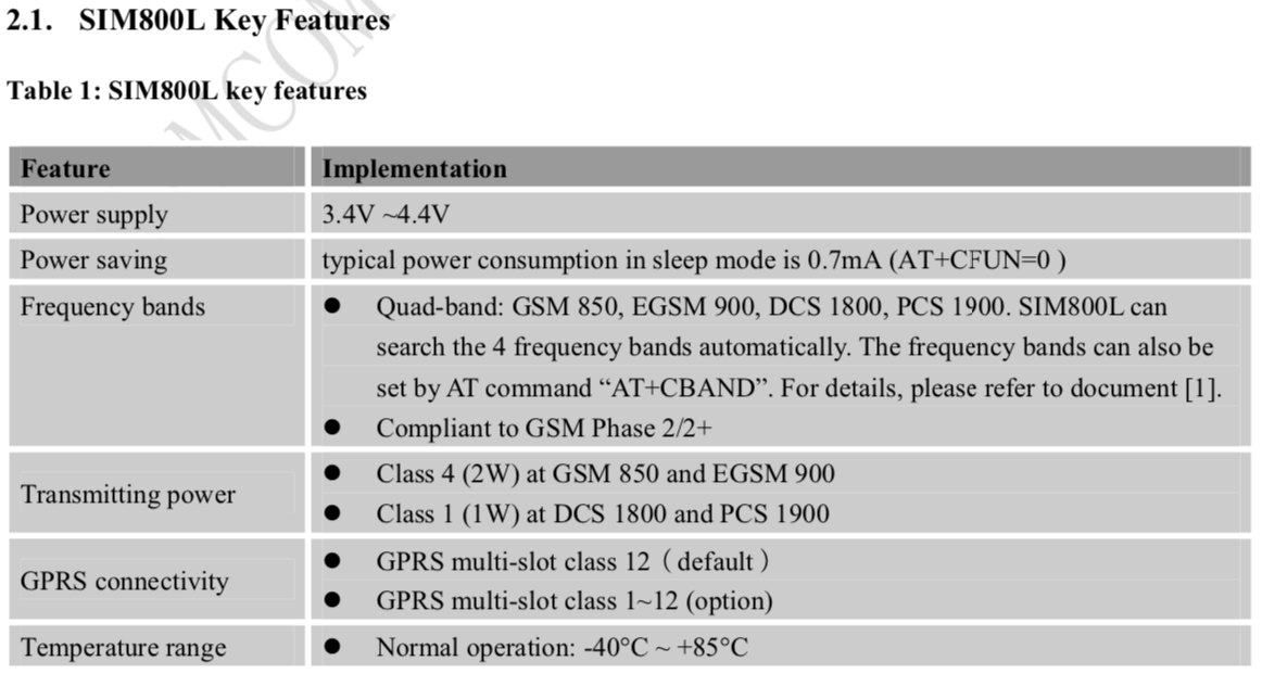
Sim800l This module uses a working voltage of 3.4 Volt Dc - 4.4 Volt Dc where we can't use directly from the 5 Volt Arduino as the sim800l voltage supply. We have to use an additional module that can lower the voltage from 5 Volt Dc to 3.4 V - 4.4 V according to the sim800l module datasheet. What I use is the sim800l V1, which is different from the Sim800l V2, we will discuss this difference in another article.

To lower the voltage I use an LM2596 Dc-Dc Buck Converter. 


We can set the output voltage of this module according to what we want. For the Sim800l Voltage Supply I use 3.7 Volt Dc. For setting the voltage on the blue Potentio. Power this module from Arduino's 5V voltage and Arduino's GND
Pins used:
  • 5V Arduino = In+ (Modul)
  • GND Arduino = In- (Modul)
"After this module is given a voltage of 5V from Arduino, the potential setting lowers the voltage to 3.7 Volts to become the sim800l supply voltage"

Note : There are many failures here where when we do Arduino Coding on the serial monitor it says "Power Check Failed" this is because the voltage does not match the sim800l can be excessive and can be lacking, so friends just set it at 3.7 Volts Dc using buck converter LM2596. And the important thing is that the Lm2596 input uses 5V Arduino and Arduino GND. In another article I will write "How to Overcome Power Check Failed Sim800l"


The circuit as above for the pin pin that I use is
  • 5V (Arduino) = IN+ (Modul LM2596)
  • GND (Arduino) = IN- (Modul LM2596)
  • OUT+ (Modul LM2596) = VCC (Sim800l)
  • OUT- (Modul LM2596) = GND (Sim800l)
  • D8 (Arduino) = TX (Sim800l)
  • D7 (Arduino) = RX (Sim800l)
Sorry, the circuit drawn may not match the actual conditions of the sim800l module, so friends, you can follow from the information I have written above. After we try the circuit above and don't forget sim800l uses a voltage of 3.7 Volts. To try it, please enter the GSM micro sim and to see the success of the sim800l, it can be seen from the sim800l led indication. If it is blinking slowly at intervals of about 2 seconds, it means that sim800l is ready to use.

To try it enter this program
/*
Sketch: Sim800l
***************************************************************************
note: the following pins has been used and should not be used for other purposes.
  pin 8   // tx pin
  pin 7   // rx pin
***************************************************************************
*/
#include <gprs.h>
#include <SoftwareSerial.h>

GPRS gprs;

void setup() {
  Serial.begin(9600);
  while(!Serial);
  Serial.println("GPRS - Send SMS Test ...");
  gprs.preInit();
  delay(1000);
  while(0 != gprs.init()) {
      delay(1000);
      Serial.print("init error\r\n");
  }  
  Serial.println("Init success, start to send SMS message...");
  gprs.sendSMS("085233xxxxxx","hello,world"); //define phone number and text
}

void loop() {
  //nothing to do
}

Make sure we already have the program library above which can be downloaded below
gprs.sendSMS("085697xxxxxx","hello,world");

Explanation of the code above :
on Blue number we can change the cellphone number that we will use to receive messages from the sim800l module and blue writing "Hello, world" we can replace it with another text as a message that will be sent by this sim800l.

Note : While trying, please look at the serial monitor, if the serial monitor receives a message "Init success, start to send SMS message..." it means this module is ready to send message and wait a while. Don't forget to make sure the sim card installed on the sim800l has a pulse, hehe, I've had the experience of being confused why I can't send messages, it turns out that the gsm simcard that I installed had no credit, just sharing experiences.

So this simple article "Simple and successful Arduino sim800l circuit" hopefully it's useful and if you have questions, you can comment below, I'll accept criticism too, if there are improvements to writing, you can also comment, I'll fix it for the sake of making the article useful greetings from me the author reyjewish-electronic.blogspot.com
"Alhamdulillah"

Recent Posts