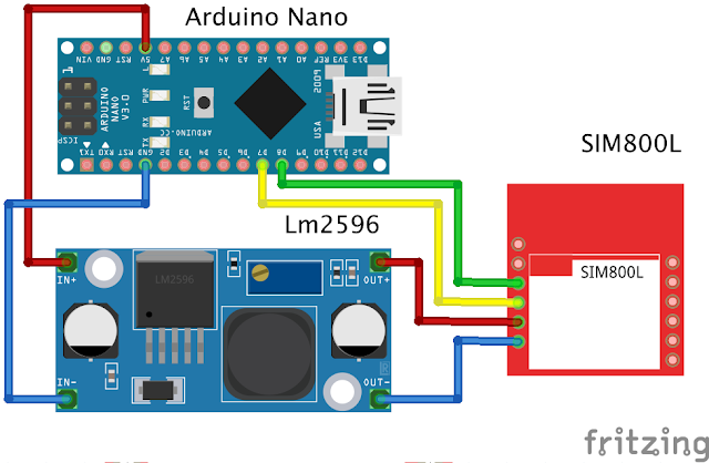
This time I shared a circuit from Arduino and SIM800l. I made this article because many of my friends find it difficult to use an SMS module, namely sim800l. This series is based on my experience so far in the field of electronics playing with sim800l so it can be imitated, tried or criticized haha, I also read a lot of comments "The power isn't strong if you take it from Arduino" my answer is "please try it first" good luck.
Langsung saja saya beri Rangkaian Sederhana Sim800l dengan arduino.
- Arduino Nano
- Buck Converter Lm2596
- Sim800l V1
Before we try the circuit above, we should get used to reading the datasheet of the module that we will use or reading articles on Google as our initial knowledge of conducting electronic circuit experiments.
Sim800l This module uses a working voltage of 3.4 Volt Dc - 4.4 Volt Dc where we can't use directly from the 5 Volt Arduino as the sim800l voltage supply. We have to use an additional module that can lower the voltage from 5 Volt Dc to 3.4 V - 4.4 V according to the sim800l module datasheet. What I use is the sim800l V1, which is different from the Sim800l V2, we will discuss this difference in another article.
To lower the voltage I use an LM2596 Dc-Dc Buck Converter.
We can set the output voltage of this module according to what we want. For the Sim800l Voltage Supply I use 3.7 Volt Dc. For setting the voltage on the blue Potentio. Power this module from Arduino's 5V voltage and Arduino's GND
Pins used:
- 5V Arduino = In+ (Modul)
- GND Arduino = In- (Modul)
"After this module is given a voltage of 5V from Arduino, the potential setting lowers the voltage to 3.7 Volts to become the sim800l supply voltage"
Note : There are many failures here where when we do Arduino Coding on the serial monitor it says "Power Check Failed" this is because the voltage does not match the sim800l can be excessive and can be lacking, so friends just set it at 3.7 Volts Dc using buck converter LM2596. And the important thing is that the Lm2596 input uses 5V Arduino and Arduino GND. In another article I will write "How to Overcome Power Check Failed Sim800l"
The circuit as above for the pin pin that I use is
- 5V (Arduino) = IN+ (Modul LM2596)
- GND (Arduino) = IN- (Modul LM2596)
- OUT+ (Modul LM2596) = VCC (Sim800l)
- OUT- (Modul LM2596) = GND (Sim800l)
- D8 (Arduino) = TX (Sim800l)
- D7 (Arduino) = RX (Sim800l)
Sorry, the circuit drawn may not match the actual conditions of the sim800l module, so friends, you can follow from the information I have written above. After we try the circuit above and don't forget sim800l uses a voltage of 3.7 Volts. To try it, please enter the GSM micro sim and to see the success of the sim800l, it can be seen from the sim800l led indication. If it is blinking slowly at intervals of about 2 seconds, it means that sim800l is ready to use.
To try it enter this program
/*
Sketch: Sim800l
***************************************************************************
note: the following pins has been used and should not be used for other purposes.
pin 8 // tx pin
pin 7 // rx pin
***************************************************************************
*/
#include <gprs.h>
#include <SoftwareSerial.h>
GPRS gprs;
void setup() {
Serial.begin(9600);
while(!Serial);
Serial.println("GPRS - Send SMS Test ...");
gprs.preInit();
delay(1000);
while(0 != gprs.init()) {
delay(1000);
Serial.print("init error\r\n");
}
Serial.println("Init success, start to send SMS message...");
gprs.sendSMS("085233xxxxxx","hello,world"); //define phone number and text
}
void loop() {
//nothing to do
}
Make sure we already have the program library above which can be downloaded below
gprs.sendSMS("085697xxxxxx","hello,world");
Explanation of the code above :
on Blue number we can change the cellphone number that we will use to receive messages from the sim800l module and blue writing "Hello, world" we can replace it with another text as a message that will be sent by this sim800l.
Note : While trying, please look at the serial monitor, if the serial monitor receives a message "Init success, start to send SMS message..." it means this module is ready to send message and wait a while. Don't forget to make sure the sim card installed on the sim800l has a pulse, hehe, I've had the experience of being confused why I can't send messages, it turns out that the gsm simcard that I installed had no credit, just sharing experiences.
So this simple article "Simple and successful Arduino sim800l circuit" hopefully it's useful and if you have questions, you can comment below, I'll accept criticism too, if there are improvements to writing, you can also comment, I'll fix it for the sake of making the article useful greetings from me the author reyjewish-electronic.blogspot.com
"Alhamdulillah"


